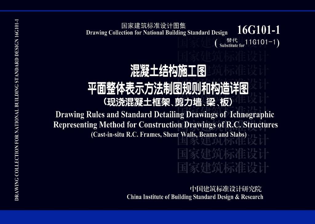
B16G101-1:中英文双语版16G101-1现行
资源类型:国标图集
发布日期:2016-09-01
实施日期:2016-09-01
废止日期:-
入库日期:2017-04-12
主编单位:
收藏
- 简介
- 目录
16G101-1 Drawing Rules and Standard Detailing Drawings of Ichnographic Representing Method for Construction Drawings of R.C. Structures (Cast-in-situ R.C. frames, shear walls, beams and slabs) is the revised version of 11G101-1 Drawing Rules and Standard Detailing Drawings of Ichnographic Representing Method for Construction Drawings of R.C. Structures (Cast-in-situ R.C. frames, shear walls, beams and slabs). According to the updated versions of codes GB 18306-2015 Seismic Ground Motion Parameters Zonation Map of China, GB50011-2010 Code for Seismic Design of Buildings and its partial revision in 2016 and GB50010-2010 Code for Design of Concrete Structures (2015 version) et al., considering feedbacks from engineering practice and need of practical projects in recent years, contents in the drawing collection have been systematically revised, and details of frame flat beams are included in this version.This drawing collection is applicable to construction drawing design of main structure in all kinds of cast-in-situ R.C. structures in seismic design with seismic precautionary intensity 6~9, such as frame structures, shear wall structures, frame-shear wall structures and partial frame-supported shear wall structures, and is also applicable to cast-in-situ R.C. slabs (with and without beams) as well as cast-in-situ R.C. walls, columns, beams and slabs of basement structures.There are two parts in this drawing collection: drawing rules of IRM and standard detailing drawings of structural members above top of the foundation, such as cast-in-situ R.C columns, shear walls, beams and slabs (with or without beams).
16G101-1中文
7
目录
7
总说明
15
第一部分 平法制图规则
17
1 总则
17
2 柱平法施工图制图规则
21
2.1 柱平法施工图的表示方法
21
2.2 列表注写方式
21
2.3 截面注写方式
25
2.4 其他
25
柱平法施工图列表注写方式示例
27
柱平法施工图截面注写方式示例
29
3 剪力墙平法施工图制图规则
31
3.1 剪力墙平法施工图的表示方法
31
3.2 列表注写方式
31
3.3 截面注写方式
39
3.4 剪力墙洞口的表示方法
41
3.5 地下室外墙的表示方法
43
3.6 其他
47
剪力墙平法施工图列表注写方式示例
49
剪力墙平法施工图截面注写方式示例
53
地下室外墙平法施工图平面注写示例
55
4 梁平法施工图制图规则
57
4.1 梁平法施工图的表示方法
57
4.2 平面注写方式
57
4.3 截面注写方式
73
4.4 梁支座上部纵筋的长度规定
75
4.5 不伸入支座的梁下部纵筋长度规定
75
4.6 其他
75
梁平法施工图平面注写方式示例
79
梁平法施工图截面注写方式示例
81
5 有梁楼盖平法施工图制图规则
83
5.1 有梁楼盖平法施工图的表示方法
83
5.2 板块集中标注
83
5.3 板支座原位标注
85
5.4 其他
91
有梁楼盖平法施工图示例
93
6 无梁楼盖平法施工图制图规则
95
6.1 无梁楼盖平法施工图的表示方法
95
6.2 板带集中标注
95
6.3 板带支座原位标注
95
6.4 暗梁的表示方法
97
6.5 其他
99
无梁楼盖平法施工图示例
101
7 楼板相关构造制图规则
103
7.1 楼板相关构造类型与表示方法
103
7.2 楼板相关构造直接引注
103
7.3 其他
115
第二部分 标准构造详图
117
混凝土结构的环境类别
117
混凝土保护层的最小厚度
117
受拉钢筋基本锚固长度
119
抗震设计时受拉钢筋基本锚固长度
119
钢筋弯折的弯弧内直径
119
受拉钢筋锚固长度
121
受拉钢筋抗震锚固长度
121
纵向钢筋弯钩与机械锚固形式
123
纵向受力钢筋搭接区箍筋构造
123
纵向钢筋的连接
123
纵向受拉钢筋搭接长度
125
纵向受拉钢筋抗震搭接长度
127
封闭箍筋及拉筋弯钩构造
129
梁并筋等效直径、最小净距
129
梁柱纵筋间距要求
129
拉结筋构造
129
螺旋箍筋构造
129
KZ纵向钢筋连接构造
131
地下室KZ的纵向钢筋连接构造
133
地下室KZ的箍筋加密区范围
133
KZ、QZ、LZ箍筋加密区范围
135
QZ、LZ纵向钢筋构造
135
抗震框架柱和小墙肢箍筋加密区高度选用表
137
KZ边柱和角柱柱顶纵向钢筋构造
139
KZ中柱柱顶纵向钢筋构造
141
KZ柱变截面位置纵向钢筋构造
141
KZ边柱、角柱柱顶等截面伸出时纵向钢筋构造
143
芯柱XZ配筋构造
145
矩形箍筋复合形式
145
剪力墙水平分布钢筋构造
147
剪力墙竖向钢筋构造
151
约束边缘构件YBZ构造
155
剪力墙水平分布钢筋计入约束边缘构件体积配箍率的构造做法
157
构造边缘构件GBZ、扶壁柱FBZ、非边缘暗柱AZ构造
159
连梁LL配筋构造
161
剪力墙BKL或AL与LL重叠时配筋构造
163
剪力墙连梁LLk纵向钢筋、箍筋加密区构造
165
连梁交叉斜筋LL(JX)配筋构造
167
连梁集中对角斜筋LL(DX)配筋构造
167
连梁对角暗撑LL(JC)配筋构造
167
地下室外墙DWQ钢筋构造
169
剪力墙洞口补强构造
171
楼层框架梁KL纵向钢筋构造
173
屋面框架梁WKL纵向钢筋构造
175
框架梁水平、竖向加腋构造
177
KL、WKL中间支座纵向钢筋构造
179
梁箍筋构造
181
非框架梁L、Lg配筋构造
183
不伸入支座的梁下部纵向钢筋断点位置
185
梁侧面纵向构造筋和拉筋
185
非框架梁L中间支座纵向钢筋构造
187
水平折梁、竖向折梁钢筋构造
187
纯悬挑梁XL及各类梁的悬挑端配筋构造
189
框架扁梁中柱节点
191
框架扁梁边柱节点(一)
193
框架扁梁箍筋构造
193
框架扁梁边柱节点(二)
195
框支梁KZL、转换柱ZHZ配筋构造
197
框支梁KZL上部墙体开洞部位加强做法
199
托柱转换梁TZL托柱位置箍筋加密构造
199
井字梁JZL、JZLg配筋构造
201
有梁楼盖楼(屋)面板配筋构造
203
板在端部支座的锚固构造(一)
203
板在端部支座的锚固构造(二)
205
板翻边FB构造
205
有梁楼盖不等跨板上部贯通纵筋连接构造
207
单(双)向板配筋示意
209
纵向钢筋非接触搭接构造
209
悬挑板XB钢筋构造
211
无支承板端部封边构造
211
折板配筋构造
211
无梁楼盖柱上板带ZSB与跨中板带KZB纵向钢筋构造
213
板带端支座纵向钢筋构造(一)
215
板带悬挑端纵向钢筋构造
215
柱上板带暗梁钢筋构造
215
板带端支座纵向钢筋构造(二)
217
板后浇带HJD钢筋构造
219
墙后浇带HJD钢筋构造
219
梁后浇带HJD钢筋构造
219
板加腋JY构造
221
局部升降板SJB构造(一)
221
局部升降板SJB构造(二)
223
板开洞BD与洞边加强钢筋构造(洞边无集中荷载)
225
悬挑板阳角放射筋Ces构造
229
板内纵筋加强带JQD构造
231
悬挑板阴角构造
231
柱帽ZMa、ZMb、ZMc、ZMab构造
233
柱顶柱帽柱纵向钢筋构造
233
抗冲切箍筋Rh构造
235
抗冲切弯起筋Rb构造
235
附录:词汇表
237
16G101-1English
8
Contents
8
General Instruction
16
Part One Drawing Rules of Ichnographic Representing Method
18
1 General Provisions
18
2 Rules of Ichnographic Construction Drawings of Columns
22
2.1 Representing method of ichnographic construction drawings of columns
22
2.2 Tabulated annotation method
22
2.3 Sectional annotation method
26
2.4 Others
26
Example of ichnographic construction drawings of columns using tabulated annotation method
28
Example of ichnographic construction drawings of columns using sectional annotation method
30
3 Rules of Ichnographic Construction Drawings of Shear Walls
32
3.1 Representing method of ichnographic construction drawings of shear walls
32
3.2 Tabulated annotation method
32
3.3 Sectional annotation method
40
3.4 Representing method of openings in shear walls
42
3.5 Representing method of exterior walls of basement
44
3.6 Others
48
Example of ichnographic construction drawings of shear walls using tabulated annotation method
50
Example of ichnographic construction drawings of shear walls using sectional annotation method
54
Example of ichnographic construction drawings of exterior walls of basement using ichnographic annotation method
56
4 Rules of Ichnographic Construction Drawings of Beams
58
4.1 Representing method of ichnographic construction drawings of beams
58
4.2 Ichnographic annotation method
58
4.3 Sectional annotation method
74
4.4 Requirements for length of top longitudinal bars in beams at support
76
4.5 Requirements for length of bottom bars in beams cut off in span
76
4.6 Others
76
Example of ichnographic construction drawings of beams using ichnographic annotation method
80
Example of ichnographic construction drawings of beams using sectional annotation method
82
5 Rules of Ichnographic Construction Drawings of Slabs with Beams
84
5.1 Representing method of ichnographic construction drawings of slabs with beams
84
5.2 General annotation of slabs
84
5.3 Specific annotation of slabs at support
86
5.4 Others
92
Example of ichnographic construction drawings of slabs with beams
94
6 Rules of Ichnographic Construction Drawings of Slabs without Beams
96
6.1 Representing method of ichnographic construction drawings of slabs without beams
96
6.2 General annotation of slab strips
96
6.3 Specific annotation of slab strips at support
96
6.4 Representing method of embedded beams
98
6.5 Others
100
Example of ichnographic construction drawings of slabs without beams
102
7 Rules for Drawings of Slab-related Detailing
104
7.1 Types and the representing method of slab-related detailing
104
7.2 Direct annotation of slab-related detailing
104
7.3 Others
116
Part Two Standard Detailing Drawings
118
Environment classification of concrete structures Minimum concrete cover
118
Basic anchorage length lab, basic anchorage length labE of tension bars in seismic design and the inside diameter of hook D
120
Anchorage length la of tension bars Anchorage length laE of tension bars in seismic design
122
Hooks and mechanical anchorage types of longitudinal bars Stirrup detailing in the lap zone of longitudinal main bars Splices of longitudinal bars
124
Lap length ll of longitudinal tension bars
126
Lap length llE of longitudinal tension bars in seismic design
128
Detailing of hooks of closed stirrups and tie bars Equivalent diameter and minimum clear spacing of twin bars in beams Spacing requirements for longitudinal bars in beams and columns Detailing of tie bars Detailing of spiral stirrups
130
Splices detailing of longitudinal bars in frame columns KZ
132
Splices detailing of longitudinal bars in frame columns KZ of basement Stirrup densification zone in frame columns KZ of basement
134
Stirrup densification zone for KZ, QZ, LZ Detailing of longitudinal bars in QZ, LZ
136
Table of height of stirrup densification zone in seismic-force-resisting frame columns or short shear wall limbs
138
Detailing of longitudinal bars at the top of edge columns and corner columns KZ
140
Detailing of longitudinal bars at the top of interior columns KZ Detailing of longitudinal bars at variable sections of columns KZ
142
Detailing of longitudinal bars at top of edge columns and corner columns KZ that rise beyond the roof with a constant section
144
Detailing of reinforcement in core columns XZ Overlapping patterns of rectangular stirrups
146
Detailing of horizontal distribution bars in shear walls
148
Detailing of vertical bars in shear walls
152
Detailing of special boundary elements YBZ
156
Detailing of special boundary elements when horizontal bars in shear walls are counted in the calculation of volumetric ratio of stirrup in special boundary elements
158
Detailing of ordinary boundary elements GBZ, buttress columns FBZ and middle embedded columns AZ
160
Detailing of reinforcement in coupling beams LL
162
Detailing of reinforcement when edge frame beams BKL or embedded beams AL of shear walls overlap with coupling beams LL
164
Detailing of longitudinal bars and stirrup densification zone in coupling beams of shear walls LLk
166
Detailing of coupling beams with crossing bars LL (JX) Detailing of coupling beams with diagonal bars LL (DX) Detailing of coupling beams with embedded diagonal bracings LL (JC)
168
Detailing of reinforcement in exterior walls of basement DWQ
170
Detailing of strengthening bars of openings in shear walls
172
Detailing of longitudinal bars in floor frame beams KL
174
Detailing of longitudinal bars in roof frame beams WKL
176
Detailing of horizontal and vertical haunch of frame beams
178
Detailing of longitudinal bars in floor and roof frame beams KL,WKL at interior supports
180
Detailing of stirrups in beams
182
Detailing of reinforcement in non-frame beams L and Lg
184
Cutoff point of beam bottom longitudinal bars which do not extend into supports Side bars and tie bars in beams
186
Detailing of longitudinal bars in beams L at interior supports Detailing of reinforcement in horizontally or vertically folded beams
188
Detailing of reinforcement in cantilever beams XL and cantilever end of all kinds of beams
190
Joints of frame flat beams and interior columns
192
Joints of frame flat beams and edge columns (Ⅰ) Stirrup detailing of frame flat beams
194
Joints of frame flat beams and edge columns (Ⅱ)
196
Detailing of reinforcement in frame-supported beams KZL and transfer columns ZHZ
198
Strengthening detailing of frame-supported beams KZL under wall openings Stirrup densification detailing of column supporting transfer beams TZL under the supported column
200
Detailing of reinforcement in #-shape arranged beams JZL or JZLg
202
Detailing of reinforcement in floor (roof) slabs with beams Anchorage detailing of slab reinforcement at end supports (Ⅰ)
204
Anchorage detailing of slab reinforcement at end supports (Ⅱ) Detailing of slab turnups FB
206
Splice detailing of top continuous bars in slabs with unequal spans
208
Schematic of reinforcement in one(two)-way slabs Detailing of non-contact lap splice of longitudinal bars
210
Detailing of reinforcement in cantilever slabs XB Detailing of reinforcement in slab free ends Detailing of reinforcement in folded slabs
212
Detailing of longitudinal bars in slab strips on top of columns ZSB and slab strips in midspan KZB of floor slabs without beams
214
Detailing of longitudinal bars at end supports of slab strips (Ⅰ) Detailing of longitudinal bars at free end of slab strips Detailing of reinforcement in embedded beams of slab strips on top of columns
216
Detailing of longitudinal bars at end supports of slab strips (Ⅱ)
218
Detailing of reinforcement in post-cast strips HJD in slabs Detailing of reinforcement in post-cast strips HJD in walls Detailing of reinforcement in post-cast strips HJD in beams
220
Detailing of haunch of slabs JY Detailing of slabs with local level difference SJB (Ⅰ)
222
Detailing of slabs with local level difference SJB (Ⅱ)
224
Detailing of slab openings BD and strengthening bars around openings (no concentrated load applied around the opening)
226
Detailing of radial bars at the external corner of cantilever slabs Ces
230
Detailing of strengthening strips of longitudinal bars JQD in slabs Detailing of the internal corner of cantilever slabs
232
Detailing of column caps ZMa, ZMb, ZMc and ZMab Detailing of column longitudinal reinforcement in column caps
234
Detailing of punching shear resistant stirrups Rh Detailing of punching shear resistant bent-up bars Rb
236
Appendix:word list
238
图书评论
暂无相关数据


 QQ好友
QQ好友 新浪微博
新浪微博 微信扫一扫
微信扫一扫


我也要评论